


DCC Wiring Basics
Digital Command Control (DCC) revolutionized model railroading by allowing independent control of multiple locomotives on the same track. But to get reliable operation, you need good wiring practices. This guide explains the fundamentals of DCC wiring: power buses, feeders, wiring for turnouts and accessories, handling reversing sections, protection and debugging, and practical examples and diagrams. Whether you’re starting a new layout or upgrading an old DC layout, this article will help you plan and implement robust DCC wiring.
Table of contents

- What DCC wiring is and how it differs from DC
- Core components: command station, booster, throttle, track, decoders
- The power bus and feeders: what they are and why they matter
- Wire gauges, color coding, and connectors
- Power districts, boosters, and protection
- Wiring turnouts and frogs (electrofrog vs. plastic frog)
- Reversing loops and auto-reversers
- Accessory and signal wiring (decoders, LEDs, point motors)
- Track detection and occupancy wiring basics
- Programming track wiring
- Troubleshooting and debugging tips
- Example wiring diagrams: simple loop, reversing loop, turnout with frog switching
- Safety and best practices
- Conclusion
What DCC wiring is and how it differs from DC
In DC layouts, voltage on the rails controls train speed; each isolated block is controlled separately. DCC, by contrast, places a constant voltage digital signal on the rails. Locomotives decode commands addressed to them and control their own motors and functions. That means:
- The track is typically one electrical block fed by the DCC booster.
- Locomotive movement is controlled digitally, not by track voltage alone.
- Short circuits are handled by the booster’s current limiting or by circuit breakers.
Because the DCC signal must reliably reach every decoder-equipped locomotive, wiring should minimize voltage drop and avoid intermittent connections.
Core components
- Command station: generates the DCC signal and controls throttles. Some command stations include integrated boosters.
- Booster: amplifies the DCC signal and supplies power to the track. Large layouts use multiple boosters for power districts.
- Throttles (or throttles via Wi-Fi/smart devices): operator interfaces.
- Track: rails carry the DCC signal.
- Decoders: install in locomotives and accessories (turnout and signal decoders) to respond to commands.
- Accessory decoders: control turnouts, lights, signals.
- Circuit protection devices: breakers or fuses.
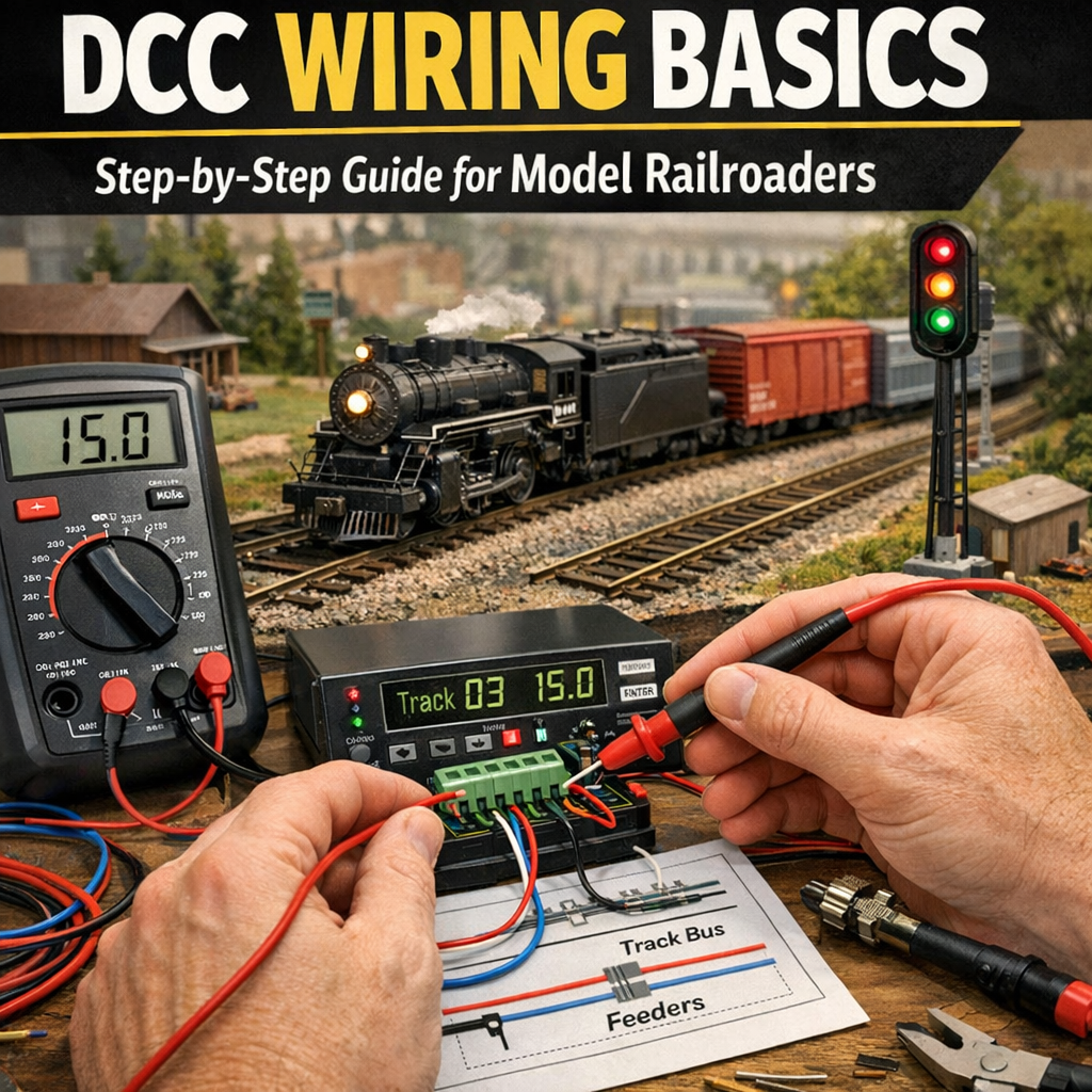
The power bus and feeders: what they are and why they matter
A good power distribution starts with the power bus and feeders.
- Power bus: heavy-gauge wires (two conductors) that run the length of the layout under the benchwork. This is the backbone for track power.
- Feeders: smaller wires connecting the track rails to the bus at regular intervals.
Why use a bus and feeders?
- Minimizes voltage drop on long layouts.
- Ensures the DCC signal remains strong and stable.
- Localizes track faults so they don’t prevent operation across the entire layout.
Recommended practices:
- Use at least one pair of bus wires per continuous loop of track; for large layouts, use two or more buses spaced apart to reduce drop.
- Add feeders to the rails every 3–6 feet (1–2 meters) for reliable power. On club layouts or heavy use, use feeders every 18–36 inches.
- Solder or use quality rail joiner crimps for reliable electrical contact—avoid relying solely on metal joiners without soldering on older or dirty rails.
Wire gauges, color coding, and connectors
Choosing the right wire gauge is essential for safety and good performance.
Common recommendations:
- Bus wires: 14–16 AWG (1.5–2.5 mm²) for medium-sized layouts; 12 AWG (3.3 mm²) for very large or many boosters.
- Feeder wires: 18–22 AWG (0.5–0.75 mm²) are common; use 18 AWG for long feeders or higher currents.
- Accessory wiring: 22–24 AWG for LEDs/signals; 20–22 AWG for slow-motion turnout motors; 18 AWG for solenoid turnout frogs.
Color coding (common convention):
- Rail A (right rail): red
- Rail B (left rail): black
- Bus pair: thicker red/black wires (or brown/blue in some countries)
- Accessory bus: separate colors (e.g., yellow/white for positives/commons), but keep consistent
Connectors:
- Use soldered connections for long-term reliability.
- Terminal blocks (Euro-style screw terminals) make modular sections and maintenance easier.
- For detachable power districts or modules, use polarized connectors like Anderson Powerpole, XLR, or heavy-duty Molex.
Power districts, boosters, and protection
Large or complex layouts should be divided into power districts. Each district has its own booster and protection device.
Why divide into districts?
- Limits the impact of shorts—only the affected district shuts down.
- Allows different power for heavy use areas (yard vs. staging).
- Simplifies wiring and troubleshooting.
Boosters:
- Command station often includes a booster; additional external boosters are used for more power.
- Booster rating example: a common DCC booster might be 3–5 A; big layouts may need boosters rated 5–10+ A.
- Connect boosters to the command station (often via a standard cable) or use a single booster per district.
Protection:
- Use circuit breakers or auto-resetting breakers (eg. Digitrax PM42, Circuit Breaker Matrix) on each district.
- For accessories, use fuses or protection per turnout/decoder output if available.
- Short-circuit detection: modern boosters will shut down or limit current to protect equipment.
Wiring turnouts and frogs
Turnouts (points) are a source of DCC shorts if not handled properly—especially electrofrog (metal frog) turnouts.
Types:
- Insulfrog (plastic frog): electrically dead frog, simplest for DCC because there’s no polarity issue. But poor wheel pickup on the frog can be a problem for short wheelbase locos.
- Electrofrog (metal frog): electrically live frog that must be powered and have correct polarity depending on route.
- Live-frog turnouts require a method to change the frog polarity when the frog is switched.
Frog wiring options:
- Use a turnout decoder with frog polarity switching built in (many Tortoise and solenoid decoders include this).
- Use an electronic frog juicer (auto-clip) which detects wheel presence and powers the frog accordingly.
- Route frog power through the turnout motor/decode so the frog switches polarity automatically.
Example: wiring an electrofrog with Tortoise slow-motion motor and an accessory decoder
- Rail feeders remain directly connected to the bus.
- The Tortoise motor is powered by an accessory decoder output; the decoder also toggles a frog output that controls the frog’s polarity.
- Make sure frog output is only live when the frog is properly isolated from the rest of the track with insulated rail joiners.
Insulated rail joiners:
- Use them to isolate the frog and the ends of the switch rails as needed.
- Proper gaps are crucial—double-check with a continuity tester after installation.
Reversing loops and auto-reversers
Reversing loops flip the electrical polarity of one rail relative to the rest of the layout, causing a DCC short unless handled.
Options to manage reversing sections:
- Manual isolation: using a switch to change polarity when a train enters/exits (tedious).
- Electronic auto-reverser: automatically detects polarity conflict when a train connects the loop, momentarily interrupts track power, and flips the loop polarity to match the mainline. Recommended for most layouts.
- Insulate the rails at both ends of the reversing section.
Wiring example (ASCII diagram):
Simple plan:
Command Station/Booster
|
±– Bus (Red/Black) ————+
|
Mainline
|
Insulated joiners
|
Reversing Section
|
Auto-Reverser Module
|
Connections back to Bus
- The reversing section is electrically isolated from the main bus and connected to the auto-reverser module, which connects to the main power bus and flips its polarity as needed.
Practical tips:
- Make the reversing section only as long as necessary.
- Add buffers/insulation on turnouts leading into the reversal.
- Ensure reliable insulated joiners and clear documentation of feed points.
Accessory and signal wiring (decoders, LEDs, point motors)
Accessory decoders convert DCC commands into actions for turnouts, signals, and lights.
Accessory wiring tips:
- Use a separate accessory bus for decoders and solenoids to keep heavy current spikes from the track bus.
- Decoders typically have:
- Command inputs (from track DCC)
- Accessory outputs (to motors/solenoids/LEDs)
- Power may be drawn from track or separate auxiliary power
- For LEDs, use current-limiting resistors. Many accessory decoders can drive LEDs directly and have built-in resistors—check specifications.
Turnout motors:
- Solenoid (fast) turnouts draw short bursts of current; use decoder outputs rated for the current or use a decoder with relay drivers.
- Slow-motion (Tortoise-style) consume low continuous current; many decoders directly drive them.
- Consider local capacitors or separate power supply for solenoids to handle the surge without resetting boosters.
Signal wiring:
- If signals are servo or LED-based, use an accessory decoder with appropriate output capability.
- Color-code wiring and label signal addresses in your wiring diagram.
Track detection and occupancy wiring basics
Detection lets blocks report occupancy, enabling automation, signaling systems, and turnout locking.
Common methods:
- Current-sensing occupancy detectors: detect current flow to a track section and assert occupancy.
- Infrared or optical sensors: for non-contact detection (useful for staging and hidden tracks).
- Reed switches/magnets: for precise detection.
Wiring considerations:
- Define detection blocks with insulated rail joiners and feed them with separate detection feeders.
- Use current detection modules (commercial modules or Arduino-based detectors) and wire them to your control system (e.g., signal system, CTC, RR&Co).
- For current detection, ensure good rail connections and solid feeder wiring; noisy connections can give false positives/negatives.
Example: simple occupancy block layout
- Isolate the block with rail gaps.
- Feed the block with its own feeder(s).
- Connect feeders to the input of the occupancy detector and to the track bus as required.
- Outputs of the detector go to the control panel or signaling system.
Programming track wiring
Programming track is a small isolated section where you can program decoders without affecting the main layout.
Best practices:
- Use an isolated piece of track connected to the programming output of the command station (many have a dedicated programming output).
- Use insulated rail joiners to isolate programming track from the rest of the layout.
- Keep programming track short and accessible.
- For programming on the main layout (Ops mode), some command stations allow programming while the locomotive is on the mainline, but be cautious—errors can cause unintended actions.
Wiring example:
- Connect the programming track to the programming track terminals on the command station.
- Ensure no other connection ties that track to the main bus.
Troubleshooting and debugging tips
When problems occur, follow a systematic approach.
Steps:
- Isolate the problem: Which boosters/districts/throttles are affected?
- Check for shorts: Use the command station’s short indicator or a multimeter to find continuity between rails where there should be none.
- Verify feeders and joints: Loose or dirty rail joiners are common culprits. Re-solder or clean rails if necessary.
- Test with a known-good loco: Confirms whether the issue is the track or the decoder-equipped loco.
- Suspend operation and inspect turnouts: Incorrect frog polarity or touching point rails cause issues.
- Use a multimeter:
- Check DCC voltage across rails (should be a square wave—not suitable for RMS DC reading but you can check for presence).
- Measure voltage drop across long runs; significant drop indicates insufficient feeders.
- Try removing sections: Disconnect sections of track or devices until the short disappears to locate fault.
- Inspect decoders: Poorly wired decoders or solder bridges can create problems.
- Look for stray wires: During construction, bare wires can get pushed under ballast and cause shorts.
Common mistakes:
- Too few feeders causing sluggish performance or decoder resets when load increases.
- Reversing sections without auto-reverser or proper isolation.
- Frog polarity not being switched on electrofrogs causing repeated shorts.
- Using too-thin wire for bus causing voltage drop and overheating.
Example wiring diagrams
- Simple DCC loop (single booster)
Command Station/Booster
|
±– Bus pair (thick red/black) under bench
|
±– Feeder – track rail A (red)
±– Feeder – other track rail B (black)
(feeders every 3–6 feet)
- Reversing loop with auto-reverser (conceptual)
Booster Bus —- Mainline —-| insulated joiner |—- Reversing Section —- Auto-Reverser —- connected back to Bus
(Booster protects this district)
- Turnout with frog switching (electrofrog + Tortoise + decoder)
Bus Feeder -> rails
–> turnout switch rails (insulated joiners)
–> Tortoise motor controlled by accessory decoder
–> decoder frog output connected to frog insulated island
When decoder throws turnout it also toggles frog polarity.
Safety and best practices
- Disconnect power before soldering or changing wiring.
- Keep wiring tidy—use cable ties and label wires.
- Avoid leaving bare wire ends; use heat-shrink or terminal blocks.
- Use appropriate wire gauge—don’t under-size feeders.
- Use surge protection and properly rated power supplies.
- Ventilate while soldering, and use eye protection.
- Document your wiring: keep a wiring diagram and label terminals and wires.
Conclusion
Good DCC wiring is the foundation of a reliable, enjoyable model railroad. Use a solid bus and frequent feeders to minimize voltage drop, divide large layouts into power districts with boosters and circuit protection, plan for turnout and frog wiring, and handle reversing sections with auto-reversers or careful isolation. Accessory and signal wiring should be planned and documented, and occupancy detection should be installed with insulated blocks and robust feeders. With proper wire gauges, consistent color coding, sane connectors, and methodical troubleshooting, your DCC layout will run smoothly and be easy to maintain. Start with good wiring habits from the outset—it’s the single best investment you can make for long-term reliability.

